Building A Custom Water Cooled PC

Contributor Ted Porter


Introduction & Components Used

There are many different approaches to building a custom PC from scratch and this is just one of them. I must also state that I am not a "modding" expert but I do have some experience of building PC's.

First chose an appropriate case which suites the type of PC that you wish to build. That might be a mini ATX case, up to a full size tower case with water cooling capabilities.

In this instance I have chosen the CM Storm Stryker Case as it will officially allow up to XL-ATX (Extra Long - length) motherboards and at a push E-ATX (Extended - width) motherboards. It will also allow you to fit a 240mm water radiator in the roof of the case.

You should keep in this information in mind when building a new system as most of the 'Enthusiasts Overclocking' motherboards are XL-ATX and E-ATX in size.

Below is a photo of the components that I purchased for this particular build and below that, I have listed each component for your information.


CoolerMaster CM Storm Stryker Water Cooling Case Modification

  1. CoolerMaster CM Storm Stryker Case
  2. Asus Rampage IV Extreme Motherboard
  3. Intel Core i7-4930K Hexa-Core Processor 3.4GHz 12MB Cache LGA 2011
  4. Corsair Dominator Platinum with Corsair Link Connector — 1.5V 16GB 2133Mhz Quad Channel DDR3 Memory Kit
  5. Corsair Memory Accessories / Dominator Platinum Light Bar Upgrade Kit
  6. Corsair AX1200i Digital ATX Power Supply — 1200 Watt 80 PLUS Platinum Certified Fully-Modular PSU
  7. Corsair PSU Accessories / Professional Individually Sleeved DC Cable Kit, Type 3 (Generation 2), WHITE
  8. Corsair PSU Accessories / Professional Individually Sleeved ATX 24 Pin Cable (Generation 2), WHITE
  9. NZXT 8 Pin (EPS12V) White Sleeved 25cm Extension Cable)
  10. NZXT 30cm Front Panel Premium White Sleeved Cables
  11. NZXT 24 Pin ATX Power Supply Premium White Sleeved 25cm Extension Cable
  12. NZXT White 4 SATA 90 degree Data to 4 SATA Data Cables
  13. Akasa 4 Pin Molex PSU Cable 30cm Extension x 5
  14. Samsung 256GB 2.5-inch SSD 840 Pro Series x 4
  15. ZOTAC GeForce GTX TITAN AMP! Edition (ZT-70102-10P)
  16. ZOTAC GeForce GTX 580 AMP! Edition (ZT-50102-10P)
  17. Noctua NF-A14 FLX 140x140x25mm, square frame 3-pin, 1200/1050/900rpm x 1
  18. Noctua NF-F12 PWM 120x120x25mm 4-pin PWM, 1500/1200rpm max. Focused Flow System x 11
  19. Scythe 120mm Fan Guard 12 Chrome x 5
  20. EK CPU Water Block EK-Supremacy CSQ - Nickel / Plexi
  21. EK Full Motherboard Water Block EK-FB KIT CSQ RE4 - Nickel / Plexi
  22. XSPC EX240 Slim Line Dual Fan Radiator
  23. XSPC / Laing D5 Vario Motor, with RPM Wire 1200lph
  24. XSPC Nylon Dual 5.25 Bay Reservoir for Laing D5 - Black
  25. XSPC Coin Fit G1/4 to 3/8 ID 5/8 OD Compression Fitting - Black Chrome x 10
  26. XSPC Twin Wired White 5mm LEDs with 4 Pin - Black - 30cm x 10
  27. XSPC Twin Wired White 3mm LEDs with 4 Pin - Black - 30cm x 4
  28. Tygon R3603 Hose 15.9/9.5mm (3/8 ID) Clear 3m
  29. Thermochill EC6 Non Conductive Coolant - Clear 2l
  30. PrimoChill Anti-Kink Coils 5/8" - Pearl 2m

The majority of my purchases were made from Novatech Ltd and Watercooling UK. At the time of writing this article, Novatech specially sourced a lot of components which are not readily available in the UK and Watercooling UK were exceptionally helpful in guiding me with my first watercooling project.

Back to Menu Tabs

Stripping the Case Down

Let's start by un-boxing and taking a look at the case.

CM Storm Stryker Case Modification

CM Storm Stryker Case Modification

Now to remove those side panels to take a look at what's inside, evaluate what needs to be removed and to get some idea of what modifications are possible. Remember to have some small pots to keep all of those screws in that you are going to remove. You don't want to find you cannot put something back because a fitting is missing!

CM Storm Stryker Case Modification

CM Storm Stryker Case Modification

CM Storm Stryker Case Modification

Having had a good look around, we now need to start removing all of the parts that can naturally be removed. I started with the front bezels, then the drive cages. There is also a 'case parts" compartment right at the bottom behind the bezel with the CoolerMaster logo on it. This will also need to be removed, as an additional 120mm floor mounted fan can be installed there to increase the airflow over the HDD's/SSD's.

CM Storm Stryker Case Modification

CM Storm Stryker Case Modification

The Storm Stryker also has a dedicated SSD drive cage at the base of the case and this to needs to be removed as another 120mm fan can be fitted in its place for additional system cooling. To remove the cage we must first put the case on its side and remove the dust filter to expose the four retaining screws.

CM Storm Stryker Case Modification

CM Storm Stryker Case Modification

Whilst the case is on its side, we will take the opportunity to remove the rear 140mm exhaust fan.

CM Storm Stryker Case Modification

Now to stand the case upright again to remove the top 200mm exhaust fan. However, the retaining screws for the top fan can only be accessed by removing the cases top cover and front panel. Fortunately, this is held on with 3 lugs on either side and can be release fairly easily.

CM Storm Stryker Case Modification

CM Storm Stryker Case Modification

CM Storm Stryker Case Modification

With the top cover removed, another fan filter is found, which when removed allows access to the top fan retaining screws.

CM Storm Stryker Case Modification

CM Storm Stryker Case Modification

We are now left with an empty shell and a pile of parts! Take care not to lose anything. Find some boxes to put the parts in until needed again.

CM Storm Stryker Case Modification

CM Storm Stryker Case Modification

CM Storm Stryker Case Modification

With the case empty, the next stage is to start working on the modifications specific to your particular system requirements.

Back to Menu Tabs

Adding Fans To A Windowed Side Panel

Some cases come with windowed side panels and some do not. Some come with fan holders pre-installed and some do not. The Storm Stryker case that I have purchased has a windowed side panel without fans.

Some people feel that if you have a windowed side panel it should remain unobstructed, to fully show off the inside of the case. In my opinion, that is fine if you are water cooling the graphics card but I am not.

As I intend to have two graphics cards in my build, I want to have as much airflow over them as possible. To this end, I will show you here how to add two fans to a windowed side panel.

CM Storm Stryker Side Panel Modification

For this part of the build you will require 2 x 120mm fans, 2 x 120mm fan filter covers and 2 x 120mm fan guards. I also suggest that you get an extra pair of hands to assist with the cutting, as you will need to lock the side panel tight to ensure a clean cut.

First of all, you need to work out where you want the fans to go, taking into account where the CPU cooler might obstruct the graphics cards position, and any other obstructions that might have a bearing on the position of the fans.

CM Storm Stryker Side Panel Modification

CM Storm Stryker Side Panel Modification

Next mark out the holes for the fan mountings and carefully drill. Make sure you do not push too hard or go too fast, as the Perspex may crack! If the Perspex has a protective covering on it, leave it on to add protection. Also place some wood blocks under the panel to help support the Perspex.

CM Storm Stryker Side Panel Modification

CM Storm Stryker Side Panel Modification

Next we need to mark where to core cut the hole for the air intake to go. To find the centre point, draw diagonal lines between the corner holes that we have just drilled.

CM Storm Stryker Side Panel Modification

CM Storm Stryker Side Panel Modification

Now for the tricky part - we need to hole saw the air intakes. I have used a 114mm hole saw, which yields a 120mm cut hole. Do not use a bigger size or you will be drawing air in around the sides!

Remember, unless you can firmly secure the side panel, get another pair of hands to assist as I did.

CM Storm Stryker Side Panel Modification

Then repeat the process for the second fan, so that you end up with two 120mm air intake holes and 4 fan screw fastening positions for each fan.

CM Storm Stryker Side Panel Modification

CM Storm Stryker Side Panel Modification

CM Storm Stryker Side Panel Modification

As the cutting process generates quite a lot of heat, you will need to clean up the holes carefully with a sharp flexible knife, making sure not to scratch the Perspex in the process.

CM Storm Stryker Side Panel Modification

CM Storm Stryker Side Panel Modification

As the case I am using is white, I want my fan grills to match. The Silverstone fans grills that I chose to use only come in black, so time for some spray painting using Simoniz acrylic white.

CM Storm Stryker Side Panel Modification

CM Storm Stryker Side Panel Modification

When spray painting the rear of the fan grill, make a template and cover the mesh to reduce paint build up which could affect the airflow.

CM Storm Stryker Side Panel Modification

Try and spay a little at a time and build it up over 4 - 6 coats. Make sure that you leave at least a couple of hours between coats. I applied 4 coats to the back of the fan grill and 6 coats to the front. I did not cover the front mesh, as I needed to spray white the black plastic on top of the mesh.

CM Storm Stryker Side Panel Modification

CM Storm Stryker Side Panel Modification

We are now ready to put all of the parts together. I am replacing all of the CoolerMaster fans in my case with Noctua fans, as they provide good airflow, static pressure and are very quiet even at 1500rpm. They also come with a 6 year warranty, which reflects the build quality of these fans.

CM Storm Stryker Side Panel Modification

When mounting the fans, make sure that you have them in the right orientation to draw air into the case. All fans should be marked with an airflow indicator.

CM Storm Stryker Side Panel Modification

With the fans in the correct position, offer them up to the holes in the side panel and loosely secure the fan covers. You will need the longer type of fan fixing screws as you are going through a fan filter, the Perspex and then into the fan. The standard size is 5mm x 10.5mm and the longer types are 5mm x 16mm - silver or black.

CM Storm Stryker Side Panel Modification

CM Storm Stryker Side Panel Modification

CM Storm Stryker Side Panel Modification

Then repeat this for the second fan and then tighten the screws carefully, making sure not to over tighten to avoid cracking the Perspex.

CM Storm Stryker Side Panel Modification

Finally, we just need to add the fan guards. I am using Scythe fan guards with silver 5mm x 10.5mm fan screws.

CM Storm Stryker Side Panel Modification

CM Storm Stryker Side Panel Modification

You now have a customised windowed side panel with 2 x 120mm cooling fans!

CM Storm Stryker Side Panel Modification

CM Storm Stryker Side Panel Modification

Back to Menu Tabs

Drive Cage Air Flow Modification

The next objective in this build is to create a greater airflow from the front intake fans into the body of case to increase the system's cooling capabilities.

To do this, I decided to customise the back of the drive cages to accommodate a second fan. This type of configuration is commonly known as "push/pull".

The drive cages in the Cooler Master Storm Stryker come with a 120mm white LED fan attached to the front. This is wired via the cage's effective cable management system on the side of the cage. So, let's remove the fan now.

CM Storm Stryker Drive Cage Modification

Use a flat blade screw driver to lift the cable retaining tabs holding the fan power connector cable.

CM Storm Stryker Drive Cage Modification

CM Storm Stryker Drive Cage Modification

The front of the drive cage obviously has pre-drilled and tapped holes but they are an American size 6-32 UNC. I will be converting the drive cage fittings to metric by tapping the holes out to M4.

CM Storm Stryker Drive Cage Modification

The rear of the cage does not have any mounting points and the aperture is 130mm x 125mm, so a 120mm fan will fall right through. There are also rivets that will hold fittings off from making a flush contact with the drive cage. These will need to be removed!

CM Storm Stryker Drive Cage Modification

We will also need to remove 5.25" drive cage guides from each side of the cage, whilst we are making our modifications.

CM Storm Stryker Drive Cage Modification

CM Storm Stryker Drive Cage Modification

First, let's drill out those rivets with a 3mm drill bit. Don't use anything larger, as you will not be able to tap the holes to M4! Once drilled, tap the holes with an M4 tap.

CM Storm Stryker Drive Cage Modification

Now we have the rivets removed, it's time to fabricate a plate that we can attach flush to the drive cage. The plate will need to also allow for the mounting of a 120mm fan.

The plate is made from a sheet of aluminium 300mm x 300mm x 2 mm thick grade 485 H14/1050. This can be purchased relatively cheaply from eBay.

As mentioned the drive cage is 130mm x 125mm, so mark out the aliminium sheet and you should be able to get 4 out of the sheet as you can see from the picture below. The sheet was cut using a band saw, so make sure that you maximise the clean cut outside edges when cutting.

CM Storm Stryker Drive Cage Modification

Once you have cut out your plates, use the drive cage's pre-drilled holes as a template and mark the holes for the fan. When drilling use a 2.5mm drill bit for M3 threads and a 3.5mm drill bit for M4 threads.

CM Storm Stryker Drive Cage Modification

CM Storm Stryker Drive Cage Modification

Use the correct machine screw thread size for the hole that you have drilled and check that your tapped holes will accept the machine screw thread.

CM Storm Stryker Drive Cage Modification

Now we need to cut the 120mm hole to allow the air to flow through. Next drill a pilot centre hole ready for the 114mm hole saw. Remember that this will cut a hole 120mm in size!

CM Storm Stryker Drive Cage Modification

Before cutting, make yourself some sort of jig to hold the aluminium securely in place or you could end up bending the aluminium, as I did on my first attempt!

Drill slowly and at a slight angle, so that not all of the teeth of the hole saw make immediate contact and thus cause you to snag.

CM Storm Stryker Drive Cage Modification

Next mark out the position of the rivet holes that you drilled and tapped earlier onto the plate. Drill using a 4mm drill and counter sink using a 6mm drill. It is alright to use a 4mm drill here, as the M4 machine screw only needs to pass though the hole.

CM Storm Stryker Drive Cage Modification

CM Storm Stryker Drive Cage Modification

Once all of the holes have been drilled, offer the plate up to the drive cage and check that the screws will position into place. I have used countersunk M3 x 8mm machine screws. Also check that the fan fits.

CM Storm Stryker Drive Cage Modification

CM Storm Stryker Drive Cage Modification

Remove the fan and machine screws from the plate and mark out and cut a key way to allow the fan power cable to pass through.

CM Storm Stryker Drive Cage Modification

When you are happy that the plate is drilled correctly and that everything fits together, it's time to start spraying! To ensure that the spray paint adheres to the aluminium surface, give each side 6 coats of Etch Primer. Then they will be ready for the top coat of black to match the drive cage. I also applied 6 coats of black, allowing about 2 hours in between sprays.

CM Storm Stryker Drive Cage Modification

CM Storm Stryker Drive Cage Modification

When the plate is fully sprayed, screw it back onto the drive cage and spray one more to cover the machine screws, so that they blend in.

CM Storm Stryker Drive Cage Modification

CM Storm Stryker Drive Cage Modification

As in section 3, the rear fan is going to have a fan guard as it will be near cabling. The front fan does not need a fan guard. So let's fit the rear and front fans. Make sure that as before you get the air flow direction right and make sure that the power cables allow good routing positions.

CM Storm Stryker Drive Cage Modification

CM Storm Stryker Drive Cage Modification

CM Storm Stryker Drive Cage Modification

Route the fan power cable via the drive cage routing tabs and the access slot that was cut into the custom fan mounting plate. I have also added a power extension cable to the front fan so that it can easily reach a power source.

CM Storm Stryker Drive Cage Modification

Finally, replace the drive cage 5.25" guides and we are all done and ready to put the customised drive cage back into the case.

CM Storm Stryker Drive Cage Modification

Back to Menu Tabs

Case Roof Water Cooling Push/Pull Modification

The Cooler Master Storm Stryker case by default allows a roof mounted water cooled radiator (240mm or 280mm), with 2 fans (either 120mm or 140mm) to be installed. It does not however permit what is called a push/pull configuration.

I would best describe this as being 2 fans mounted to the bottom of the radiator pushing cool air over it and 2 fans mounted above pulling hot air away from the radiator.

The objective therefore for this stage of the build, is to modify the case's carrying handle located in the roof to allow such a configuration.

CM Strom Stryker Push/Pull Case Handle Radiator Modification

Let’s start by removing the case's roof cover to expose the carrying handle and its fixings.

CM Strom Stryker Push/Pull Case Handle Radiator Modification

The roof of the case is held on by 6 plastic clips, 3 on either side. To release the clips, push the tabs inwards away from the underside of the roof frame.

CM Strom Stryker Push/Pull Case Handle Radiator Modification

Now that we have clear access to the area we need to work on, let us investigate which fastenings need to be removed, to facilitate the detachment of the handle form the case.

CM Strom Stryker Push/Pull Case Handle Radiator Modification

CM Strom Stryker Push/Pull Case Handle Radiator Modification

On closer inspection, the handle is held on by stainless steel rivets. The front of the handle has the head of the rivet exposed, so a 3mm titanium high speed tip drill bit should make light work of that. Or will it! In fact I broke one drill trying to do this. The trick was to put the drill on maximum RPM and firmly push, as opposed to my original approach which was to drill slowly using a light touch.

CM Strom Stryker Push/Pull Case Handle Radiator Modification

The rear of the handle is also secured using stainless steel rivets, except these ones are inverted. Access from below is limited, so drilling them out is not such a viable option as there will be a chance of the drills chuck fowling the case.

CM Strom Stryker Push/Pull Case Handle Radiator Modification

CM Strom Stryker Push/Pull Case Handle Radiator Modification

I did try to drill the rivets out from above but the drill bit kept slipping. In the end I got a small hacksaw blade and cut the rivet off and then cleaned the hole with a 3mm drill bit.

CM Strom Stryker Push/Pull Case Handle Radiator Modification

CM Strom Stryker Push/Pull Case Handle Radiator Modification

At last, to my relief the handle was free with just a few scratches that can easily be resolved.

CM Strom Stryker Push/Pull Case Handle Radiator Modification

CM Strom Stryker Push/Pull Case Handle Radiator Modification

With the handle removed, we need to offer it up with some test fans in place. As you can see, the handles feet are off the case's surface by quite a few degrees. Time to start fashioning a new handle shape!

CM Strom Stryker Push/Pull Case Handle Radiator Modification

I bent my handle purely "by eye" but I am sure that someone will have a scientific way of doing it! I would stress that using my method you take your time and do not hit it with a metal hammer! As you can see from the picture below, I used G-clamps, wood blocks and a rubber mallet.

Also after every bend I made, I went back to the case and checked the shape of the handle against the fans. This whole process took about an hour and even then when I thought I had it right it was not. I had forgotten to check it in place with the roof of the case on. You will notice in subsequent pictures that there are two unwanted drill holes. Learn from my mistake!

CM Strom Stryker Push/Pull Case Handle Radiator Modification

CM Strom Stryker Push/Pull Case Handle Radiator Modification

As the handles rear fixing point is now circa 20mm in the air, the question is how to secure it. I have used stainless steel tubing to make posts, which has an opening large enough to pass an M4 machine screw through.

Stainless steel is quite hard to cut accurately, so don't worry about getting the length exact or the ends completely flat, as you can always shim them out with washers.

CM Strom Stryker Push/Pull Case Handle Radiator Modification

CM Strom Stryker Push/Pull Case Handle Radiator Modification

CM Strom Stryker Push/Pull Case Handle Radiator Modification

As you can see, there is now a nice clearance for the fans to reside in. These fans are just my test fans and when I get to the radiator fitting stage, I will be using the Noctua NF-F12 PWM 120mm Focused Flow PWM Cooling Fans.

CM Strom Stryker Push/Pull Case Handle Radiator Modification

Now to tidy up those scratches on the handle. As in my previous sections, I have used etch primer and acrylic black spray paints. You will note that I have completely covered the rubber grip to ensure that no paint gets on to it.

Although I have not shown it here, I have also sprayed the stainless steel posts black to match the handle.

CM Strom Stryker Push/Pull Case Handle Radiator Modification

All that is now needed is to fit the case's roof top back. You will need to remove both the roof cover and the handle again, when it comes to fitting the radiator and push pull fan configuration.

CM Strom Stryker Push/Pull Case Handle Radiator Modification

Back to Menu Tabs

Component Testing & CPU Installation

As there is such a large array of components to be integrated within this build, it is best if possible to test the main components (CPU, memory and motherboard) outside of the case. From experience, I have fallen foul of putting a build together, only to find that the system will not boot up due to something like failed memory or an unknown hardware incompatibility.

To save money on purchasing a professional test bench, I bought some commercial foam and extra large anti-static bags and covered the foam with the anti-static bags, using insulated electrical tape to stick it all together. This makes a good safe base to place your motherboard onto, to start adding components.

Asus Rampage IV Extreme - Intel Core i7-3930K

Now that I have a base to install the components on, I next proceed to install the CPU into the motherboard's CPU socket. As my motherboard is an X79 variant, it has a Socket 2011 processor fitment. You will find that the CPU socket has a cover on it to protect the socket which will need to be removed.

This is done simply by carefully pulling it away from the CPU retention bracket. When you have complete this, you will see that there are two lever arms which are anchored behind two tabs. Move the levers to the sides to release the mechanism and the CPU socket will then be fully exposed.

Asus Rampage IV Extreme - Intel Core i7-3930K

Here is a close-up of the CPU socket and note the keys on the edges. It is very important that when installing the CPU that you match the keys of the socket to the exact same keys on the CPU.

Asus Rampage IV Extreme - Intel Core i7-3930K

To ensure that I do not damage the underside of the CPU I have kept it in its protective packaging but you can still see its corresponding key to the CPU socket.

Asus Rampage IV Extreme - Intel Core i7-3930K

Next carefully place the CPU over socket, making sure that it is fully aligned to the keys. Try and get the CPU as close as possible to the socket without actually making contact and then you should find that you can release the CPU and it should gently move into place.

Asus Rampage IV Extreme - Intel Core i7-3930K

For testing purposes, I have used a cheap a budget air cooler, as I will not be overclocking the CPU at this stage. I will also not be detailing in full here the mounting of the CPU cooler. I would like to however draw your attention to a very important part of this process which I have not shown. This is applying TIM (Thermal Interface Material) to the CPU to ensure heat dissipation between the CPU and CPU cooler, whether it be an air or water cooler. I will cover this in another section when I fit the CPU water block.

Asus Rampage IV Extreme - Intel Core i7-3930K

Next install the memory and once again I am not going to detail this here but it will be covered fully in another section.

Asus Rampage IV Extreme - Intel Core i7-3930K

The same goes for the disk drive (HDD or SDD) but you will need to connect one for system testing.

Asus Rampage IV Extreme - Intel Core i7-3930K

Finally, install a graphics card (I just used an old GTX440 for testing purposes) and the PSU (power supply unit). Connect your mouse, keyboard and monitor just as you would if it were all in a case and power on.

Asus Rampage IV Extreme - Intel Core i7-3930K

Hopefully, your system components will have all passed and you should see your system BIOS on the screen. Now is a good time to update your motherboard's BIOS if it is not running the latest revision but this is a whole new topic that I will need to cover, along with overclocking in a future article.

Back to Menu Tabs

Fitting The Radiator Into The Case

Now the fun begins! In section 5, you will have seen the modification of the case handle to facilitate the fitting of two fans above the radiator for a push/pull configuration. In this section, you will now see how it all comes together.

I am using the XSPC EX240 Dual Fan Radiator (dimensions 121 x 35.5 x 275mm (WxDxH)), as I have a depth restriction once the bottom fans are fitted. A radiator of a large depth, would foul on the motherboard. It is very important that you work these factors out prior to purchasing your components.

XSPC EX240 Dual Fan Radiator Push/Pull

Before you fit your radiator, put a little of the coolant into the radiator to give it a quick washout to make sure that there are no unwanted foreign bodies from the manufacturing process. The radiator should be clean but I prefer to be absolute. On the point of coolant; I was going to use a pastel white coloured coolant but under advisement from Watercooling UK  I was directed to the Clear Thermochill EC6 Non Conductive Coolant as it is less likely to cause a build up of impurities overtime in the water cooling loop.

XSPC EX240 Dual Fan Radiator Push/Pull

With your radiator flushed out, next is the installation of the pipe fittings. I have used XSPC Coin Fit G1/4 to 3/8 ID 5/8 OD Compression Fittings but you could use barbs and clips. Installing the compression fittings is very simple and all I needed was a 2 pence piece but you could use a 1 pence piece also.

XSPC EX240 Dual Fan Radiator Push/Pull

XSPC EX240 Dual Fan Radiator Push/Pull

XSPC EX240 Dual Fan Radiator Push/Pull

With the compression fittings installed we are all set to anchor the roof fans through the top of the case into the radiator. I purchased additional screws, as the radiator only came with 4 x 6-32 UNC x 1¼" machine screws. Do not exceed this length and do use M3 machine screws, otherwise you will damage the radiator thread.

XSPC EX240 Dual Fan Radiator Push/Pull

XSPC EX240 Dual Fan Radiator Push/Pull

As you can see, the radiator is now securely fitted into place. I am not going to fit the second set of fans under the radiator yet, as there is a logical installation order of components that must be followed to ensure that once a component is fitted, it does not have to be removed to facilitate the installation of another component.

XSPC EX240 Dual Fan Radiator Push/Pull

I have fitted my radiator with the compression fittings towards the front of the case. The reason being that I will need a shorter length of tube to go from the upper drive bay reservoir to the radiator, which should improve flow though the system. With the upper fans in place and the radiator secured, we can now re-fit the modified case handle.

XSPC EX240 Dual Fan Radiator Push/Pull

XSPC EX240 Dual Fan Radiator Push/Pull

Strom Stryker Push/Pull Case Handle XSPC EX240 Radiator Modification

Finally, we can put the case roof back on to see that it all fits in place. I will remove the case roof whilst installing the remainder of the components but for now job done.

XSPC EX240 Dual Fan Radiator Push/Pull

Back to Menu Tabs

Motherboard Posts & IO Shield Installation

Most cases do not come with the posts pre-installed for the motherboard to sit on. They will certainly not have the correct IO Shield installed, as this will come as part of your motherboard package. The CM Storm Stryker has two pre-installed posts which have ridged locator tops to help make sure that the motherboard fits correctly onto the posts.

Motherboard Posts & IO Shield Installation

Depending on the size of motherboard you have, you will need to install the posts into the appropriate designated threaded holes. If you are not sure which holes to use, carefully offer your motherboard into the case and make a note of where the retaining holes in your motherboard site. Then just simply screw the posts into place. You will need a small socket set or as I am using, a purpose made socket screw driver.

Motherboard Posts & IO Shield Installation

Motherboard Posts & IO Shield Installation

Next get the IO Shield that was supplied with your motherboard and fit in into the IO Shield opening on the case. There may already be a generic one fitted, so just remove it.

Motherboard Posts & IO Shield Installation

Motherboard Posts & IO Shield Installation

Lastly offer you motherboard onto the posts. Try and place the motherboard at a very slight angle into the IO Shield first and then lower onto the posts. I found that this way made it easier when trying to marry up the motherboard's connector interfaces with the IO Shield.

Motherboard Posts & IO Shield Installation

Motherboard Posts & IO Shield Installation

Normally, if you were using air cooling you would now secure the motherboard to the posts using the screws supplied with your case. As this system is going to be water cooled, I still need to work on the motherboard outside of the case.

Back to Menu Tabs

CPU & Full Motherboard Water Block Installation

This section along with the forthcoming section on building a custom water cooling loop, is one of the more intricate areas of the build and you should follow the manufacturer's installation instructions to the letter. The narrative that I have produced here is only a guide and not a definitive method.

This part of the process is specific to the Asus Rampage IV Extreme motherboard but the methodology can be applied to other motherboards. Firstly, we need to completely remove the existing heat pipe cooling system from the motherboard, so begin by turning the motherboard upside down and locate the heat pipe, VRM (Voltage regulator module) and MOSFET retaining screws.

You can find out more about MOSFETs here What is a MOSFET, what does it look like, and how does it work?  if you are interested.

EK-Supremacy - EK-FB KIT CSQ RE4 - Nickel/Plexi

With the screws removed, turn the motherboard upright and carefully remove the Southbridge fan power cable using a small flat bladed screw driver.

EK-Supremacy - EK-FB KIT CSQ RE4 - Nickel/Plexi

EK-Supremacy - EK-FB KIT CSQ RE4 - Nickel/Plexi

Now you can safely remove the motherboard heat pipe cooling system to expose the Southbridge chip, VRM's and MOSFET areas.

EK-Supremacy - EK-FB KIT CSQ RE4 - Nickel/Plexi

The Southbridge chip will have a lot of TIM (Thermal Interface Material) on it, which will need to be cleaned off.

EK-Supremacy - EK-FB KIT CSQ RE4 - Nickel/Plexi

To remove the old TIM, you will need something like an ArctiClean Kit (includes 30ml Thermal Material Remover and 30ml Thermal Surface Purifier), plus some lint free cloth and some cotton buds for the awkward places.

EK-Supremacy - EK-FB KIT CSQ RE4 - Nickel/Plexi

You now need to apply so fresh TIM to the Southbridge chip and using the retaining screws supplied with your motherboard water block, secure it to the motherboard. Then do likewise with the VRM and MOSFET water block but you will also be supplied with thermal pads to enhance further the dissipation of heat. With regards to TIM, I personally use Noctua NT-H1 or in this instance, I am using GELID Solutions GC-Extreme.

EK-Supremacy - EK-FB KIT CSQ RE4 - Nickel/Plexi

The EK-Supremacy CPU water block that I am using, comes with three different flow plates - J1, J2 and J3. By default J2 is installed but for socket 2011 processors we need to change it for the J3 flow plate, which allows a greater flow of water through the block.

EK-Supremacy - EK-FB KIT CSQ RE4 - Nickel/Plexi

To change the flow plate, turn the CPU water block upside down and remove the four retaining screws using the supplied 'Allen' key.

EK-Supremacy - EK-FB KIT CSQ RE4 - Nickel/Plexi

Now carefully lift the back plate away from the block to reveal the J2 flow plate. Once again, carefully remove this from the rubber seal and place the J3 flow plate back onto the rubber seal. Then replace the back plate, being careful not to over tighten the retaining screws.

EK-Supremacy - EK-FB KIT CSQ RE4 - Nickel/Plexi

EK-Supremacy - EK-FB KIT CSQ RE4 - Nickel/Plexi

With the block back together again, whilst the block is not installed onto the motherboard, install the compression fittings. It is better to to it this way, so as not to apply any unnecessary pressure to the CPU socket.

EK-Supremacy - EK-FB KIT CSQ RE4 - Nickel/Plexi

EK-Supremacy - EK-FB KIT CSQ RE4 - Nickel/Plexi

Now to install the compression fittings onto the motherboard water blocks. Take great care not too apply to much pressure as they are now sitting on top of delicate motherboard components.

EK-Supremacy - EK-FB KIT CSQ RE4 - Nickel/Plexi

Next install the CPU alignment and retention posts. On socket 2011, the CPU mounting back plate is pre-installed and thus makes the CPU block installation very simple. Note that throughout this installation the CPU socket has the protective shipping cover over it and I suggest that you do the same.

EK-Supremacy - EK-FB KIT CSQ RE4 - Nickel/Plexi

Time to remove the CPU protection cover and apply the TIM. I have shown this time the TIM being applied. There are various schools of thought how TIM should be applied but I always use the "two rice grain" method and place it in the centre of the area I wish to bond.

EK-Supremacy - EK-FB KIT CSQ RE4 - Nickel/Plexi

Carefully lower the CPU water block down over the alignment and retention posts until the base touches the CPU. Then using the retention locking thumb screws, by hand evenly tighten the the CPU block in place until the locking thumb screws will turn no more. Do not over tighten.

EK-Supremacy - EK-FB KIT CSQ RE4 - Nickel/Plexi

Advisory! - Whilst trying to fit my CPU water block, the bottom right-hand edge fouled on the Southbridge water block. I had to file about 0.5mm off of the corner to make it clear.

EK-Supremacy - EK-FB KIT CSQ RE4 - Nickel/Plexi

Finally, you can now fit your motherboard into the case, using the methods described in section 6.

EK-Supremacy - EK-FB KIT CSQ RE4 - Nickel/Plexi

As the motherboard is now in place, it is now a good time to fit the 8-pin ATX CPU power cable at the top of the motherboard and the two remaining fans to the underside of the radiator to complete this stage of the build. As you can see it is a very tight fit and now you know why there is an order in which each component should be installed.

EK-Supremacy - EK-FB KIT CSQ RE4 - Nickel/Plexi

I have also fitted fan guard grilles to these fans to ensure that any close cabling does not make contact with the fan blade whilst the fans are spinning and cause a breakage.

EK-Supremacy - EK-FB KIT CSQ RE4 - Nickel/Plexi

Back to Menu Tabs

Pump & Reservoir Assembly

There are various pumps and reservoirs in the water cooling market place. Some are combined pumps and reservoirs, some reservoirs mount inside the case. The combinations are very diverse and you need to decide which combination best fits your requirements and budget.

For my build I wanted a reservoir that would fit in the upper CD/DVD drive bays and had an integrated pump. Well, in part this was not to be, as the particular model I wanted was not in stock, with no end date to the next delivery. However, I have actually ended up with what I think is a better solution and saved myself a lot of money at the same time.

I still have the same XSPC brand that I wanted but it is in kit form rather than ready made. Also the pump is external to the reservoir rather than on the inside. When you think about it, having the pump outside of the reservoir makes it a lot easier when it comes to maintenance.

XSPC Nylon Dual 5.25 Bay Reservoir Laing D5 Vario Motor

Fitting the pump to the reservoir was a very easy exercise and was well documented in the instructions. All I needed do was to align the shaft of the motor in a key-way in the reservoir and then place the large O-Ring over the motor and then do the same with the locking ring and tighten until the locking ring will not turn any further. Do not force the locking ring too tight as you may damage the thread.

XSPC Nylon Dual 5.25 Bay Reservoir Laing D5 Vario Motor

XSPC Nylon Dual 5.25 Bay Reservoir Laing D5 Vario Motor

Next install the compression fittings. This process is exactly the same as for the water blocks as described in section 9. It is just worth pointing out that this motor has five speed settings and by default is set to its fastest setting of P5 which is 4,800rpm with a flow rate of 1,200lph. Not bad for a pump of this size.

One other thing, you will see that the reservoir has an inlet and an outlet. Make a note of which is which for later when you start connecting the loop up, as it will make life easier when it is mounted inside the case and you cannot see the markings.

XSPC Nylon Dual 5.25 Bay Reservoir Laing D5 Vario Motor

If you look closely at the right-hand side of the reservoir, you will see a circular recess which will take 5mm LED to illuminate the reservoir from behind, allowing you to see the coolant level from the front. I will expand further on case 'Bling' in a later section.

XSPC Nylon Dual 5.25 Bay Reservoir Laing D5 Vario Motor

All that is left to do is mount the assembled pump and reservoir into the case's upper CD/DVD drive bays. The mounting system for the reservoir is identical to that of a standard DVD drive, with four screws securing it on either side. I have also added one of the cases default front bezels for effect.

XSPC Nylon Dual 5.25 Bay Reservoir Laing D5 Vario Motor

Back to Menu Tabs

Building A Custom Water Cooling Loop

Up until now I have always been an air cooler man when it comes to CPU cooling, favouring the Nocuta NH-D14 using a three fan configuration. However, even the mighty NH-D14 is not man enough to tame an Intel Core i7-3930K Hexa-Core Processor fully overclocked! Also, most of the performance memory is now so tall (as you will see later), that it just will not fit under the fans of a CPU air cooler.

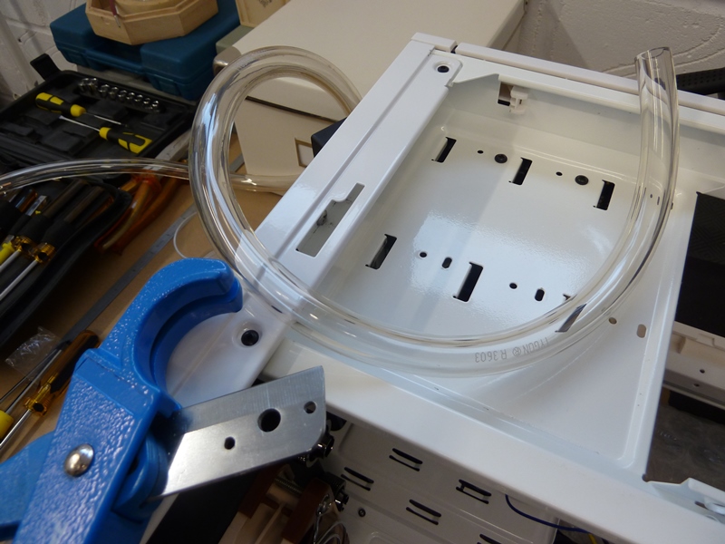
With that said, it's time to move onto building the custom water cooling loop. For this you will need a large hose cutter (10mm-40mm cut radius) and 2m-3m of good quality hose. For my loop I am using clear Tygon R3603 ⅜"ID (Inside Diameter) - ⅝"OD (Outside Diameter) size hose, which was developed for use in laboratories and hospitals originally and allows for very tight bends without kinking.

CM Storm Styker Custom Water Cooling Loop

Before you start cutting the hose, work out a plan of how you would like your loop to logically work. The design of my loop is as follows:

START - Reservoir outlet port --> Radiator inside port --> Radiator outside port --> CPU water block left port --> CPU water block right port --> Southbridge water block left port --> Southbridge water block right port --> MOSFET water block left port --> MOSFET water block right port --> Reservoir inlet port - END

When you have decided on your loop design, with the locking fitting removed from the compression fitting take one end of the hose and place it through the locking fitting and firmly push the end of the hose over the barb. Making sure that the hose is fully flush with the fitting. When you are happy, using the locking fitting, compress the hose so that it cannot leak.

Then offer the hose up to the next fitting in the loop and cut the length required. Remember when cutting the hose for the reservoir connections, leave some slack as you will need to pull out the reservoir to fill the system.

CM Storm Styker Custom Water Cooling Loop

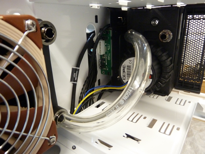
Then repeat this process until you have connected all of your fittings together using the hose to complete your water cooling loop.

CM Storm Styker Custom Water Cooling Loop

The next stage is to fill your loop. I purchased a small funnel, so that I could easily put the end of it in the fill port of the reservoir. you will need to top up the reservoir several times during the filling and air bleeding process.

CM Storm Styker Custom Water Cooling Loop

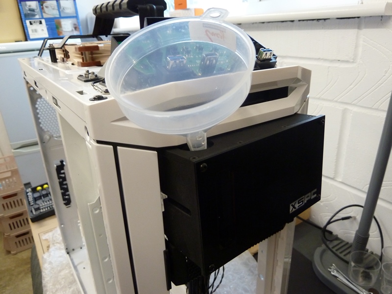
With the reservoir filled, you will need to start pumping the water around the loop. For this, I used an old PSU and a 24-pin ATX PSU bridging tool, which can be purchased extremely cheaply. The bridging tool allows the PSU to power peripherals, without the need of a motherboard.

The reason behind why you do it this way, rather than use the PSU in your case and with the power directly connected to the motherboard, is quite simple. Water and electricity don't mix! Performing the fill and air bleeding this way, eliminates any possibility of having a catastrophe should your loop leak!

CM Storm Styker Custom Water Cooling Loop

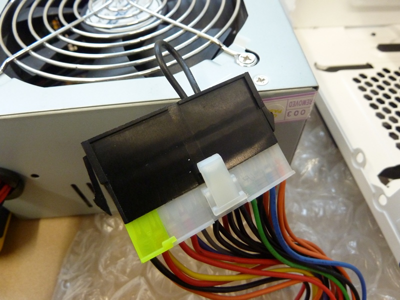
Next connect you pump to one of the PSU's 4-pin MOLEX connector and the main power to the PSU. Then blip the power on and off in short bursts, then a long single burst until you see the coolant in the hose. You will now need to refill the reservoir and repeat this procedure until both the hose and reservoir are full.

CM Storm Styker Custom Water Cooling Loop

To fully bleed the air from the system, you will need to gently rock your case from side to side, whilst bursting the power on and off to the pump. It may take quite a few attempts. The most important thing  to look for is leaks. If you find one, tighten up the compression fitting until the leak desists.

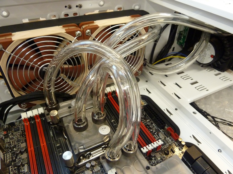
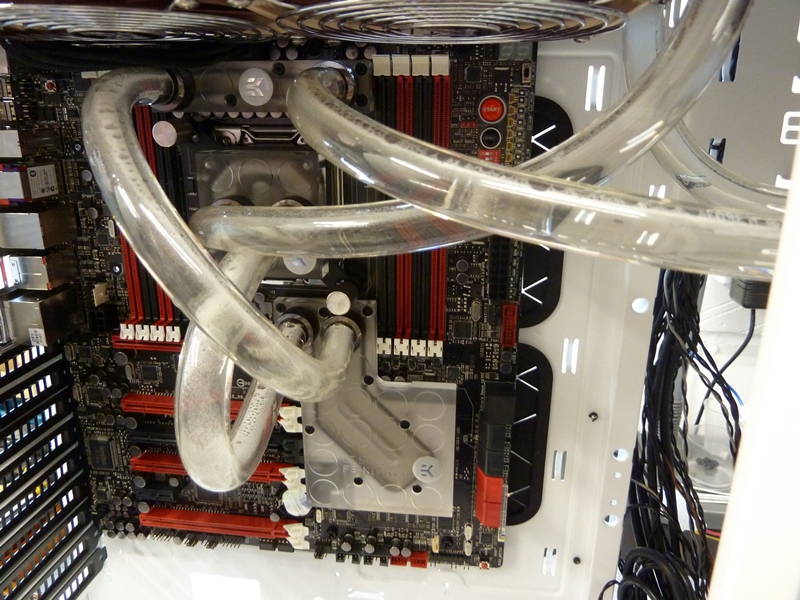
I have to admit here that after I had put my loop together, filled and bled it all that the loop from the CPU water block to the Southbridge water block was actually too long and obstructed the top PCI-E slot, where I need to put one of my graphics cards. To this end, I had to drain down the system and cut two new lengths of hose. Play spot the difference between the photo above and below!

CM Storm Styker Custom Water Cooling Loop

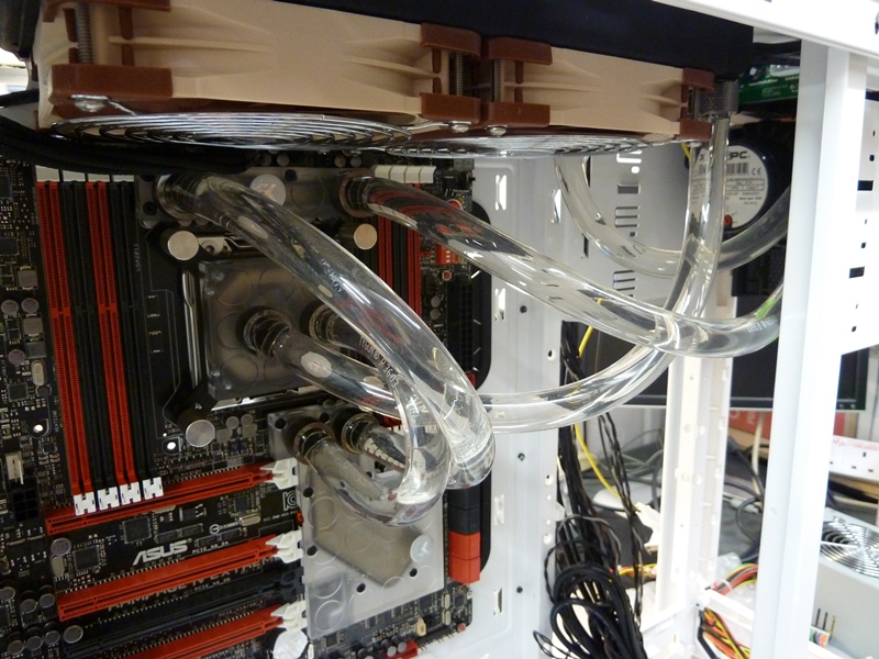
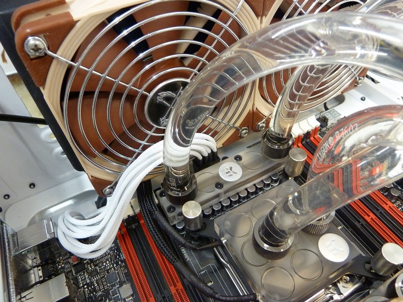
Now, in previous sections, I have gone on about having a logical build order to make sure that every thing fits, well I broke my own rule. I decided that I wanted all of my PSU's cables to be white and individually sleeved. Ergo, I had to remove one of the radiator fans, which was now rather fiddly as the water cooling loop is now in place.

CM Storm Styker Custom Water Cooling Loop

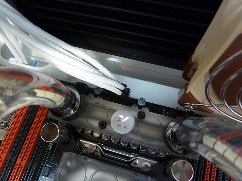
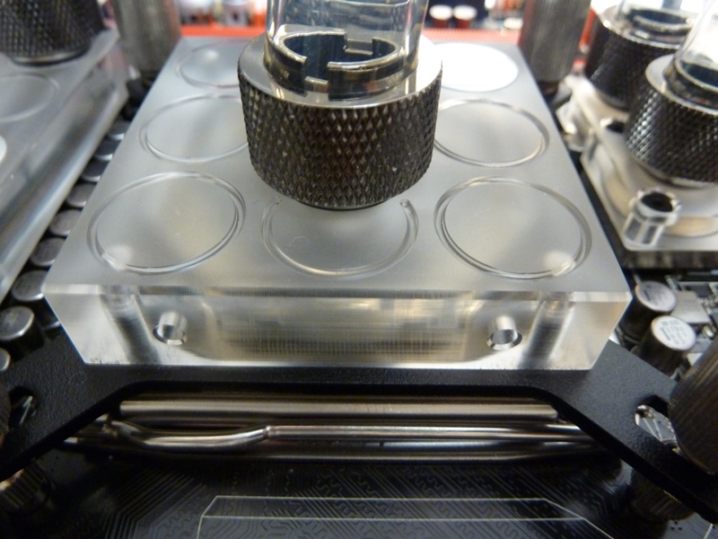
Whilst there is still good access the the CPU water block, I am going to add some 'Bling'. The water block actually has 2 x 3mm purpose made holes in the side of it, to allow you to fit some LED's.

CM Storm Styker Custom Water Cooling Loop

As the LED cables will be visible (and are black - no choice), I have tried to route them as discreetly as possible, across the top of the motherboard. I have pre-calculated that the RAM DIMMs will fit without issue as they will be using the red slots. In fact the RAM DIMMs will help hide some of the cable.

CM Storm Styker Custom Water Cooling Loop

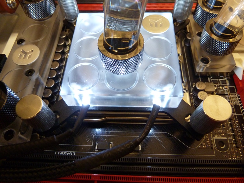
Finally, all that is needed is to test the LEDs - White of course! The connection again is using 4-pin MOLEX, so with your test PSU and bridging tool still in place turn the power on. Overkill or subtle?

CM Storm Styker Custom Water Cooling Loop

Back to Menu Tabs

Memory Installation + Light Bars

The Corsair Dominator Platinum series memory allows you at an additional cost to change the heat sink cover bar to allow a subtle lighting effect.

Corsair Dominator Platinum - Light Bars

Each kit contains two lenses each in Arctic White and Cerulean Blue. You can light two Dominator Platinum modules in the same colour or mix them for a multi-hue effect. As my theme is black and white, I will be using the Arctic White lenses.

Corsair Dominator Platinum - Light Bars

The upgrade is performed by removing the top bar and inserting a coloured lens into the replacement bar. You then need to attach the new Light Bar using the supplied Allen key.

Corsair Dominator Platinum - Light Bars

Corsair Dominator Platinum - Light Bars

Corsair Dominator Platinum - Light Bars

To install the two Light Bars takes about 15 minutes but as my motherboard requires Quad Channel memory, I had a total of 4 Light Bars to fit, which obviously took a little longer albeit a simple task. Below you can see a memory module with and without the Light Bar upgrade.

Corsair Dominator Platinum - Light Bars

With the Light Bars in place, we can now install the memory DIMM's (dual in-line memory module) into the memory slots on the motherboard. As this motherboard supports quad channel memory, two memory dimms need to be installed on each side of the CPU.

Corsair Dominator Platinum - Light Bars

As with most modern motherboards when installing memory DIMM's, you angle one side into the slot and then push down on the other side until it clicks into place and is held by the retaining clip.

Corsair Dominator Platinum - Light Bars

You will note that the DIMM's are in the Red Slots. This is because we are only using 4 memory DIMMS and the memory must be configured in alternate slots from the outside of the motherboard moving inwards towards the CPU.

Back to Menu Tabs

Solid State Drive Installation

The CoolerMaster Storm Stryker Case come with 2 drive cages that will each hold up to 4 x 3.5" or 2.5" drives. We have already used one of these drive cages in Section 4 "Drive Cage Air Flow Modification" but that is fine as I only intend to use 4 Solid State Drives in this build.

The first thing is to add a fan to the from of the drive cage to ensure that the SSD's have appropriate cooling. As I have already shown in Section 4 how to do this, I will document by using just the images as a reminder of the process. Remember to get the fan air flow going in the correct Direction.

Samsung 256GB 2.5-inch SSD 840 Pro Series

Samsung 256GB 2.5-inch SSD 840 Pro Series

Samsung 256GB 2.5-inch SSD 840 Pro Series

Also supplier with the CoolerMaster Storm Stryker Case are some excellent drive caddies for mounting the SSD's into the drive cage.

Samsung 256GB 2.5-inch SSD 840 Pro Series

Note that if you are using 3.5" drives the cadies have key-way points to align the drive with, which makes installation of the drive into the caddie very easy.

Samsung 256GB 2.5-inch SSD 840 Pro Series

As I am using 2.5" drives, I will need to mount the drives using the centre mounting points on the caddie. The mounting points are coded on the underside of the caddie to ensure that the drive is mounted in the correct location.

Samsung 256GB 2.5-inch SSD 840 Pro Series

Samsung 256GB 2.5-inch SSD 840 Pro Series

Samsung 256GB 2.5-inch SSD 840 Pro Series

Repeat the SSD caddie installation process for the remaining drives and then slide the caddies into the drive cage using the rail guides on the inside of the drive cage. The caddie will click into place once fully inserted into the drive cage.

Samsung 256GB 2.5-inch SSD 840 Pro Series

Samsung 256GB 2.5-inch SSD 840 Pro Series

Next connect the SATA cables to the drives. As the cable theme of my build is white, I purchased the NZXT White 4 SATA 90 degree Data to 4 SATA Data Cable set.

Samsung 256GB 2.5-inch SSD 840 Pro Series

Lastly, place the drive cage into the case and connect you drives to the motherboards SATA ports. I am using one of the Intel SATA 6G RED ports, which will support my SSD that will have the operating system on. For my other 3 SSD's, I have have connected them to the Intel SATA 3G BLACK ports. I will configure the 3 SSD's as a RAID-0 array, which will hold all of my FlightSim programs and data.

Samsung 256GB 2.5-inch SSD 840 Pro Series

Special Note - When connecting the SSD's make sure that you use the SATA6G_1 port for the operating system and SATA3G_1–3 ports for the RAID-0 Array. This will give you a logical list of the SSD drives reported in the ASUS BIOS and in the Intel Rapid Storage Technology Option ROM utility.

Samsung 256GB 2.5-inch SSD 840 Pro Series

Back to Menu Tabs

Case Drive Cage Re-Assembly

In this section, I am quite simply going to re-assemble the drive cage retaining mechanism back into the case, then position the drive cage that has been custom modified and the drive cage holding the SSD's within it.

CM Storm Stryker Drive Cage

I want the SSD drive cage to go at the bottom and face the cabling out towards the back of the case, rather than the conventional orientation of towards the motherboard, which makes for a neater build. I start by putting back the case rigidity bar and then the side cage rail plates.

CM Storm Stryker Drive Cage

Then I repeat the process for the middle drive cage, except this time I am going to arrange the side cage rail plates so that the cage will face towards the motherboard, so that I get the maximum amount of cooling from the double fan modification I made.

CM Storm Stryker Drive Cage

With the middle cage in this position it will help cool the graphics card as well as improve airflow into the case. I have also added a case facia blanking plate between the drive cages and XSPC dual bay reservoir.

CM Storm Stryker Drive Cage

Back to Menu Tabs

Fitting The Power Supply (PSU)

Fitting a PSU into a case is generally a very straight forward operation. Most cases sold today favour the bottom case mounted PSU, but some do still use the top of the case. There are a few cases that allow you to fit the PSU in the top or bottom of the case.

Corsair AX1200i

Simply Place the PSU into the allocated location. The case that I am using allows for air to be drawn in from the bottom of the case, so I have mounted my PSU with the fan face down. In cases that do nit have this facility, you must install your PSU with the fan faced upward.

Corsair AX1200i

With the PSU in position, look at the PSU from the back of the case and you will see four fastening positions, which I have circled in red. The PSU screws should be supplied with the case and with the PSU. You can use either set as they are a standard fitting.

Corsair AX1200i

With the four retaining screws in place, you are all done and can move onto the next task. I said that this part was easy.

Corsair AX1200i

Back to Menu Tabs

Additional Air Cooling

You may recall at the beginning of the article, that I stripped the case down and remove all of the modular components including the pre-installed fans. The fan that was fitted as standard for the rear exhaust needs to be re-installed except that I am going to use a Noctua NF-A14 FLX 140mm fan, as they are far superior to the CoolerMaster fan, in terms of performance, durability and quietness.

Noctua NF-A14 FLX

Installing the fan is a very simple task which merely requires the fan to be fastened in place using the 4 fan fixing screws supplied with the fan and then connect the fan to a suitable power source. I am not personally using any of the 3-pin fan headers on the motherboard but instead using a 3-pin to Molex power converter and running all of my fans directly from the PSU Molex connections. You do not have to do it this way but if you are overclocking, its not a bad idea to keep all the power dedicated to the CPU and PCI-E slots.

Noctua NF-A14 FLX

The CoolerMaster Storm Stryker also has 2 empty 120mm fan fixing positions in the floor of the case, to draw cool air into the case and up onto the PCI-E cards, such as a graphics card. In this build it will also provide and source of cool air for the radiator fans in the top of the case to pull cool air over the water cooling loop.

Noctua NF-F12 PWM

The CoolerMaster Storm Stryker has a sliding fan filter to protect the case from drawing in any dust that might foul the fan and reduce the cooling capability.

Noctua NF-F12 PWM

With case on its side, simply remove the sliding fan filter and prepare the fans. To keep the theme consistent, I am once again going to use two of the Noctua NF-F12 PWM fans.

Noctua NF-F12 PWM

As cables will be running over the fans from the PSU, it is advisable to fit fan guards to mitigate the chance of a cable being caught in the fan. As before I am using the Scythe 120mm fan guards.

Noctua NF-F12 PWM

With both fans having had their fan guards installed, place them in situate at the bottom of the case ready to be fixed from the bottom of the case with supplied 4 fan fixing screws for each fan.

Noctua NF-F12 PWM

Next replace the sliding fan filter, stand the case upright and fit the 3-pin power cables, as advised with the 140mm fan discussed above.

Noctua NF-F12 PWM

Now you are all set to install the PSU cables, knowing that you are not going to get a problem with a cable interfering with the fan and worse still causing some sort of electrical short, if a cable were to be stripped by a fan blade.

Noctua NF-F12 PWM

Back to Menu Tabs

LED Custom Lighting

A lot of fans nowadays come with LED lights already built into them. However, the high end fans normally do not. As is the case with Noctua fans. To this end, I decided to add some of my own custom lighting to illuminate the case. I have used a mixture of XSPC Twin Wired White 3mm / 5mm LEDs with 4 Pin power connectors, which I then converted to a Molex connection using cable conversion plug.

Adding the lights is a very simple task, so I will not go into a lot of detail. Basically all I did was find appropriately positioned pre-drilled holes in the case that would take a rubber grommet and then inserted an LED into it. The following images show just how easy if is.

XSPC Twin Wired White 5mm LEDs with 4 Pin

XSPC Twin Wired White 5mm LEDs with 4 Pin

XSPC Twin Wired White 5mm LEDs with 4 Pin

XSPC Twin Wired White 5mm LEDs with 4 Pin

It is also very easy to add lighting to the drive cages as well for an additional effect. As a point of information, if you do not intend to change the default CoolerMaster fans, you will not need to add LEDs, as these fans already have the LEDs built into them.

XSPC Twin Wired White 5mm LEDs with 4 Pin

Make sure that you test the lighting loom before you start to tidy all of those cables, as it will be a lot of work to reverse engineer the installation! As you can see, in my opinion the LEDs produce a very subtle down light. You will see the full effect of the LED lighting in my closing photos towards the end of my article.

XSPC Twin Wired White 5mm LEDs with 4 Pin

Back to Menu Tabs

Cabling & Keeping Things Tidy (including adding PCI-E Cards)

The task of cabling can be an arduous and daunting task if you have never built a PC before. What I would say is before you start, think about how you are going to route your cables and what obstacles might befall you whilst doing it. This should greatly reduce having to remove cables once installed because things are not accessible or cable will not reach where they are supposed to go. You will note from my list of components in Introduction & Components Used section, that I have used several PSU extension cables to aid the task of cabling to plugs that are right at the top of the case.

The Corsair AX 1200i by default comes with modular black cables but as I wanted this build to be more than just a standard build I separately purchased the Corsair PSU Professional Individually Sleeved white DC Cable Kit Type 3 (Generation 2) and the matching ATX 24 pin cable. If you decide to do the same, beware that the ATX 24 pin cable has to be bought separately. So to sum you have to but the PSU, the additional cable kit and the ATX 24 pin cable, all as individual purchases. Not a cheap way to go but it looks good!

How To Build Your Own PC

You may have noted from previous sections, that I had pre-installed the CPU 8 pin (EPS12V) power extension cable, as I had worked put that the plug would be obscured once the water cooling loop was installed. The detail is all in the planning!

This means that all I have to do is plug the Corsair provided CPU 8 pin cable into the extension cable and back to the PSU. With that out of the way, I next install the bulky ATX 24 pin power cable as it is normally the hardest cable to get tidy in the case. I can then fit everything else around it.

How To Build Your Own PC

How To Build Your Own PC

How To Build Your Own PC

How To Build Your Own PC

Next I add the peripheral power cables for the SSD drives and connect the SATA cables to the motherboard. As I have 4 SSD drives, I will have to be careful not to stress the SATA connectors on the motherboard or it could cause problems further down the line. The good thing with the configuration that I have chosen for the drive cages, is that all of the power and SATA cable are presented straight to the back of the case. Thus keeping things very tidy in the from of the case.

How To Build Your Own PC

How To Build Your Own PC

Now install any PCI-E cards that you have, such as graphics cards. I have 2 graphics cards and a 9 pin serial port adapter, which I connect my replica CP Flight Boeing 737 MCP to.

With the graphics cards, the PCI-E 16x slots have special tabs that will lock the card in place. So when installing the GPU card, take your time and make sure that the front plate is over the front of the motherboard and that the gold edge connector of the card is correctly lined up with the PCI-E slot.

It may seem obvious but I have seen many a PCI / PCI-E slot damaged due to brute force being used just because the card was not in the correct place prior to being pushed home into the slot.

How To Build Your Own PC

Assuming that your graphics card(s) require power, now is the time to install the power cables. Normally most quality PSUs will come with at least 4 6/8 pin PCI-E power cables to allow for more than one GPU to be installed, some people may want to run a nVidia SLI or AMD / ATI Crossfire configuration.

How To Build Your Own PC

Move onto installing the case front panel, sound and USB cables that are provided. As I want to keep them consistent, I purchased a set of NZXT 30cm Front Panel Premium White Sleeved Cables to interface to the standard case cables. When connecting these cables, always refer to the case and motherboard manuals to ensure that you connect the cables to the correct pins on the motherboard. Failure to do so could result in the front buttons not working.

How To Build Your Own PC

I have one last task due to the fact that I have added fans to my side window. I need to provide power to the fans, making sure that the cables cannot be seen through the Perspex window and spoil the look from outside.

How To Build Your Own PC

CM Strom Stryker Push/Pull Case Handle Radiator Modification

Now the mammoth task of trying to anchor and tidy the cables hanging out of the back of the case. Once again take your time and make sure that cables are not adversely bent or trapped, which could cause issues latter. I have used a mixture of black and white cable ties, along with some self adhesive cable tie anchor pads.

How To Build Your Own PC

It may take several attempts to get the cabling right to allow the back side panel to fit comfortable. Remember, if it feels tight or you are having to force the panel on, then check your cabling and adjust to suit.

How To Build Your Own PC

Time now for me to attached the power cables of the windowed side panel to power cables and check that when the side panel is fitted, the fans do not foul on any cables of PCI-E cards.

How To Build Your Own PC

As you can see from this photo, I have tried to make the cabling inside the case as neat as possible. This not only looks good but allows for a greater flow of air through the case to aid in component cooling.

How To Build Your Own PC

Having checked everything one last time and with the windowed side panel cabled, it's time to slide the panel into place, stand back and take a few moments to admire one's handy work!

How To Build Your Own PC

How To Build Your Own PC

Back to Menu Tabs

Running Up The Finished Article

With the hardware components all installed, here are a few photos of the first time I powered on the PC which I have named Deathstar III, as this is the third incarnation that I have built.

Custom PC with Water Cooling Loop

Custom PC with Water Cooling Loop

Custom PC with Water Cooling Loop

Custom PC with Water Cooling Loop

Custom PC with Water Cooling Loop

Custom PC with Water Cooling Loop

Back to Menu Tabs

Graphics Card Upgrade

Since building 'Deathstar III', I have been saving like mad and decided for my 50th birthday present to myself that I would purchase a nVidia GeForce GTX Titan!

I tend to favour the Zotac graphics cards as they give you a 5 year warranty, so I decided to stick with them. However, just as I was about to make my purchase, Zotac brought out their AMP Edition which is a factory shipped overclocked version. So I spent a little more and got it!

Zotac GeForce GTX Titan AMP Edition

Zotac GeForce GTX Titan AMP Edition

At the time of my original build I used my Zotac GeForce GTX 580 AMP Edition cards, so now I need to remove the primary card to make way for the 'Titan'! I start by removing the PCI-E 6/8-pin power cables.

Zotac GeForce GTX Titan AMP Edition

Next remove the DVI cable from the back of the card and then the two PCI-E card mounting motherboard screws. To save me unplugging everything, I performed this upgrade with the case upright in situ but I would recommend laying the case flat on a work bench. If you do perform the upgrade this way, depending on the size of the card, you may need to support the weight of the card, as so not to stress the PCI-E slot and motherboard.

Zotac GeForce GTX Titan AMP Edition

Now for part one of the tricky bit! Due to my motherboard water block being so close to the PCI-E slots butterfly lock, I need to be very careful in how I release it. I have found that an ice lolly stick to be just right for the job, as it is strong enough to exert a force on and if it slips, as it is wood will not cause any damage.

Zotac GeForce GTX Titan AMP Edition

With the butterfly lock release, I very carefully remove the graphics card, using an even pulling force on both ends of the card until it becomes free of the PCI-E slot.

Zotac GeForce GTX Titan AMP Edition

To install the new card, basically just reverse the removal process. Part two of the tricky process is to get that PCI-E butterfly lock, to fully lock the Titan in place. As you can see from the photos, it is a very tight fit, so I used a piece of string under the PCI-E butterfly lock and pull up on both sides of the string. Once again as with the ice lolly stick, if the string touches any part of the system, no damage can be done.

Zotac GeForce GTX Titan AMP Edition

So that only leaves me to power up and see just how fast this new baby goes! I have high expectations for this new mammoth of a graphics card!

Zotac GeForce GTX Titan AMP Edition

Back to Menu Tabs